VORTRIXE & CISON 1/6 4-Stroke 44cc Water-Cooled Gasoline OHV V8 Engine Model Kits
Features:
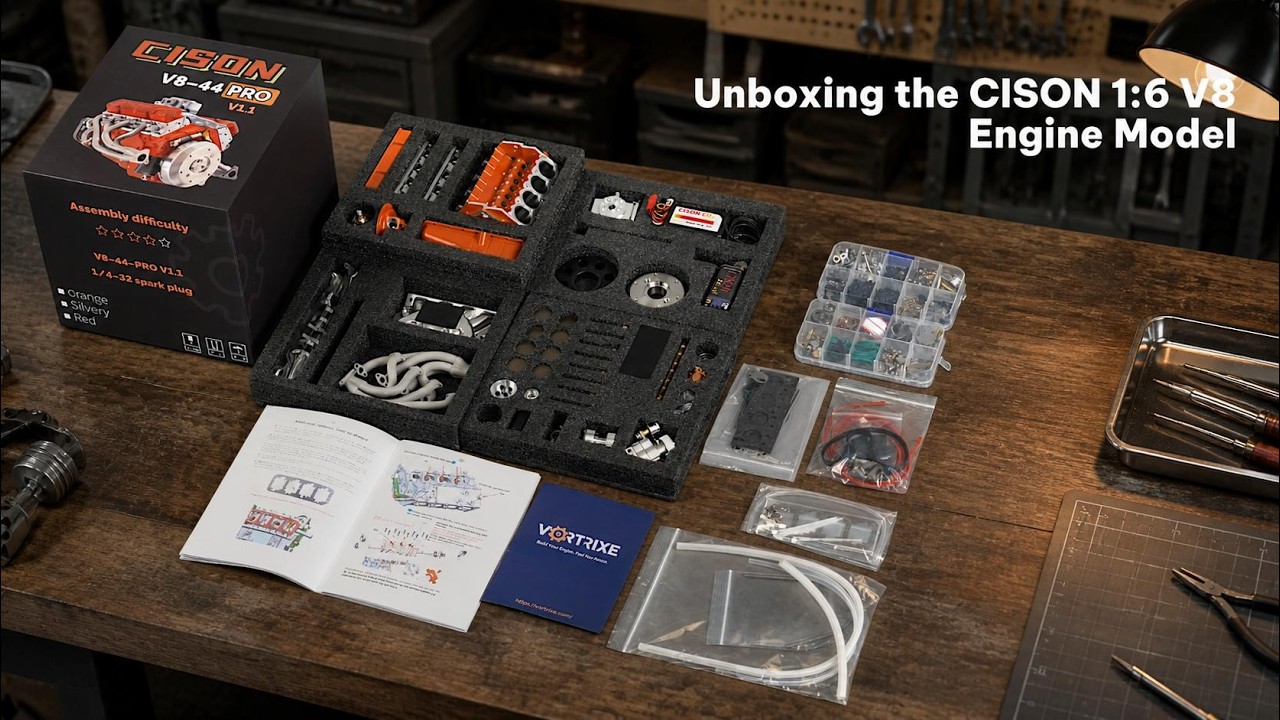
- Hands-On DIY Engine Build:
Experience the joy of mechanical assembly with high-precision components and clear instructions. Learn engine structures and working principles as you build your own functional masterpiece from scratch.
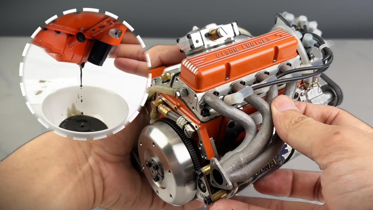
- Realistic Simulation & Functionality:
Features iconic electrophoretic orange coating and supports actual fuel-powered operation. Includes a reserved slot for generator installation, delivering both authentic appearance and mechanical performance.
- Precision CNC Engineering:
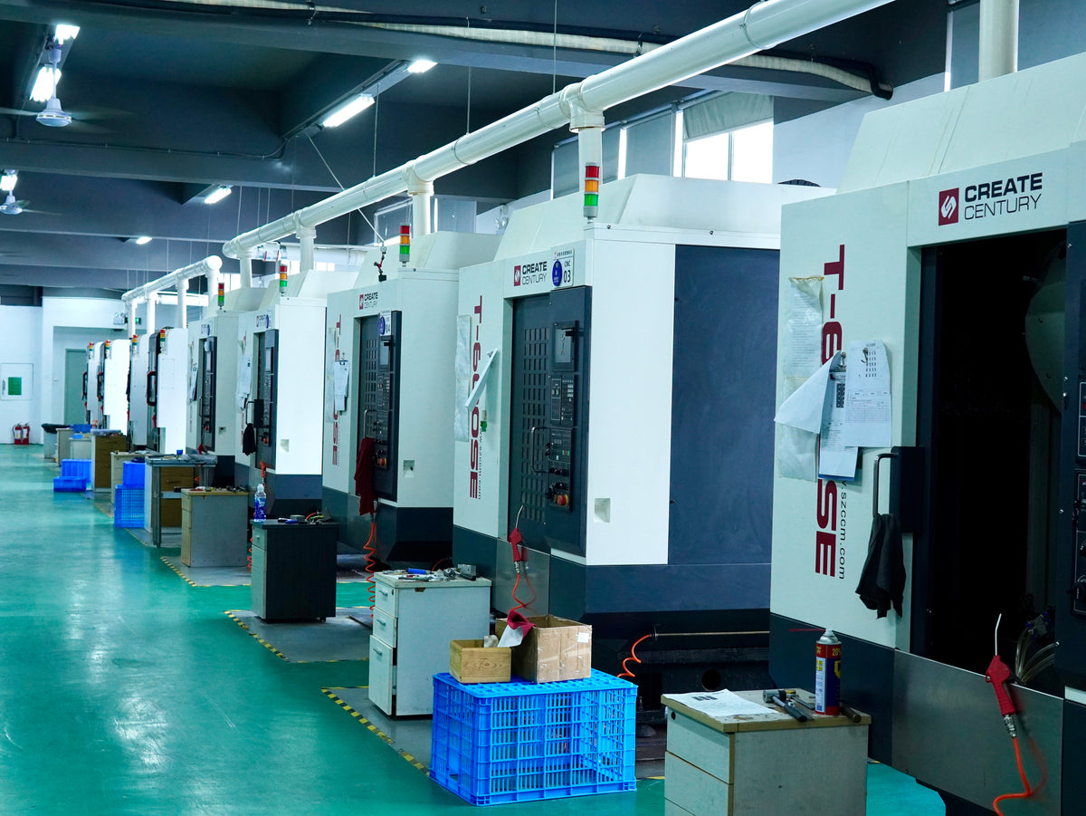
The engine block is crafted using advanced 5-axis CNC machining with a repositioning accuracy of 0.005mm, ensuring perfect fit and smooth operation for a premium mechanical feel.
- High-Torque, Stable Power:
Built with extended-stroke camshafts, larger intake valves, reinforced connecting rods, a 5-point crankshaft, and an independent lubrication system for sustained high-power output, perfect for RC applications.
- Collectible, Playable, Giftable:
Once assembled, this engine serves as a stunning desktop display, can be used to power RC models, or makes an impressive gift for mechanical enthusiasts and hobbyists.
Kind Reminder:
- This engine is a parts kit version and comes with a complimentary CDI ignition system. It does not include water cooling components, spark plug, fuel tank, fuel tubing, or engine base. Please follow the instructions carefully when assembling and operating the engine to avoid damage caused by improper use. If you have any questions, feel free to connect with us.
Product Introduction:
- CISON V8-OHV-44 PRO Engine makes a powerful debut, continuing the legacy of the original classic with a full-scale upgrade. Featuring a striking electrophoretic orange paint finish, it’s equipped with a high-angle stroke, 4-point supported camshaft, enlarged intake valves (larger than exhaust valves), a 5-point supported crankshaft, reinforced wear-resistant connecting rods, dual cast-iron piston rings (optional oil ring), independent lubrication system, a dual-layer gear-driven water pump, and optional generator support.
- This new generation addresses key issues from previous versions with precise improvements to components such as the cylinder bearings, compression ratio, pistons, and valves—resulting in enhanced DIY fun, high realism, and powerful performance. It’s not only an exceptional educational tool for exploring mechanical principles but also serves as the “power heart” for RC models, and a unique collectible or premium gift for enthusiasts.